


 29 / 36

27
27
www.rapidonline.com education@rapidonline.comPhysics
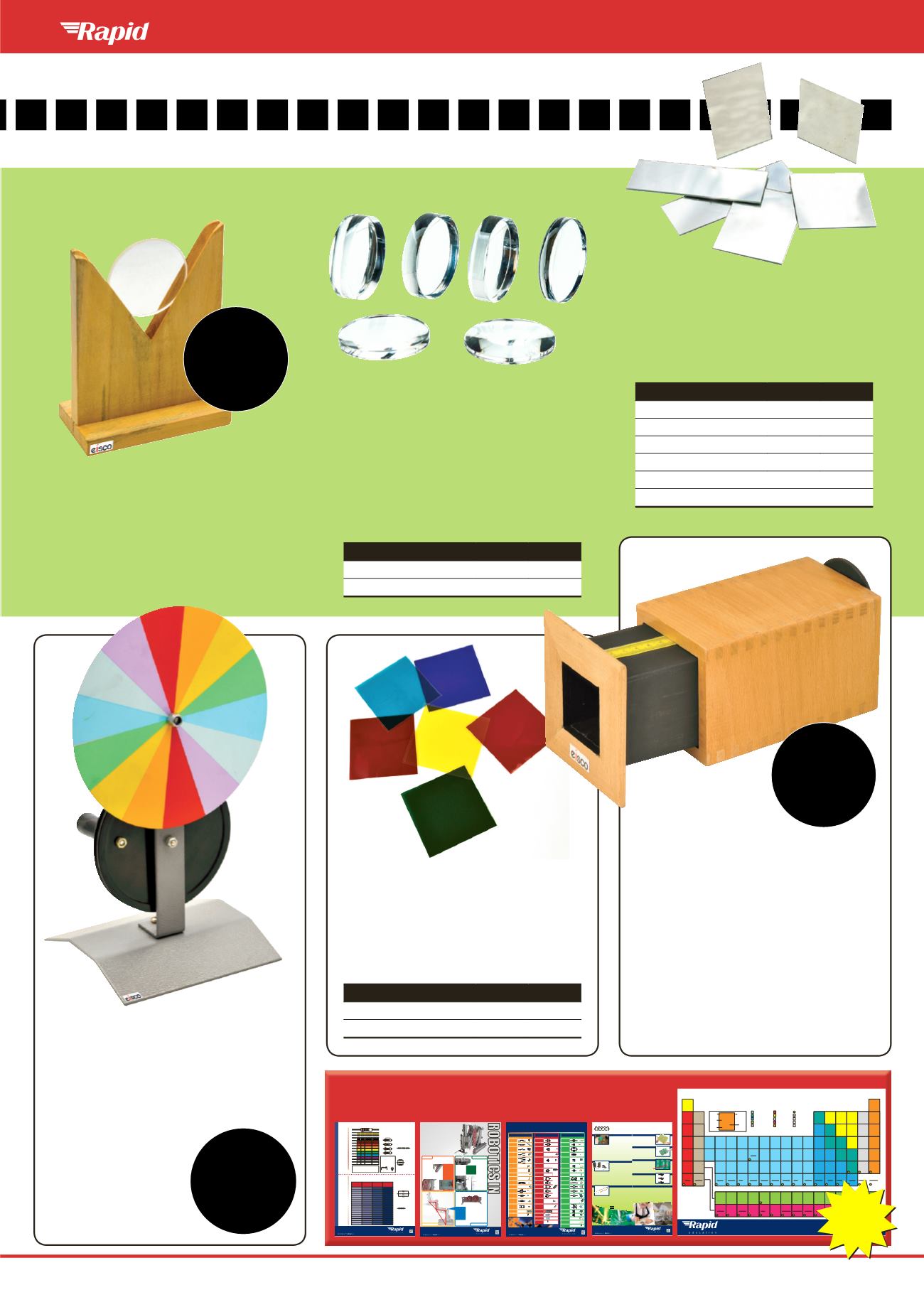
Wooden Lens Holder
A wooden holder with a V-shaped slot for
supporting lenses or mirrors up to 76mm in
diameter.
The holder consists of an upright 100mm high,
mounted on a 100 x 50mm rectangular base.
An index mark is engraved on each end of the
base for easy distance measurements.
•
Holds convex or concave lenses
•
Dimensions:100 x 100 x 50mm
•
Eisco type PH055A
Order code
52-3682
£1.79
Acrylic Lenses Set
Optical lens sets of six acrylic lenses. The lenses
have ground and polished faces and ground
edges. Each set includes one of each of: double
convex, plano-convex, converging concave-
convex, diverging concave-convex, double
concave and plano-concave.
•
Acrylic lens sets
•
Available in sets of 38mm or 50mm diameter
•
Wooden storage box with hinges and latch
•
Eisco PH0538 series
Lens diameter
Order code
1+
38mm
52-3683
£7.99
50mm
52-3684
£9.95
565656
Primary and Secondary
Coloured Filters
Sets of six coloured plastic sheets. Three sheets
feature primary colours, three feature secondary
colours.
•
Coloured plastic sheets with or without mounts
•
Supplied as
sets of 6
Type
Order code
1+
50x50mm, mounted
52-3686
£4.79
100x100mm, unmounted
52-3694
£4.19
565600
Unmounted Plane
Glass Mirrors
Silvered plane glass mirrors with a protective
coating.
•
Range of sizes
•
Supplied in
packs of 10
Size
Order code
1+
75 x 25mm
52-3688
£2.29
75 x 50mm
52-3689
£3.19
100 x 75mm
52-3690
£4.95
150 x 25mm
52-3691
£3.49
150 x 50mm
52-3692
£4.89
150 x 100mm
52-3693
£7.95
565671
Order code
52-3677
£17.95
Pin Hole
Camera
The concept of the pin-hole camera is centuries-
old. This model consists of a telescopic wooden
box with a pinhole in one end. Light rays passing
through the pinhole are projected as an image
on a translucent plate. Students view this image
through a hole in the other end and can change
the image size by changing the length of the box.
•
Demonstrates the behaviour of light
•
Eisco type PH0592
Order code
52-3687
£13.95
Newton’s Colour Disc
Newton’s colour disc demonstrates the discovery,
made by Newton, that white light is composed
of all the spectral colours. By rotating a multi-
coloured disc at high speed, the individual
colours can be seen to merge into white.
The apparatus consists of a
175mm diameter multi-
coloured disc mounted on
a metal stand. The disc is
driven by a belt connected
to a driving wheel, fitted
with a crank handle.
•
Disc diameter 715mm
•
Eisco type PH0582A
FREE SCIENCE & DESIGN & TECHNOLOGY POSTERS
for your pack
Capacitance
(picofaradpF)
Capacitance
(nanofaradnF)
Capacitance
(microfaradµF)
Capacitance
Code
10
0.01
100
15
0.015
150
47
0.047
470
82
0.082
820
100
0.1
101
330
0.33
331
470
0.47
0.00047
471
1000
1.0
0.001
102
1500
1.5
0.0015
152
2200
2.2
0.0022
222
4700
4.7
0.0047
472
6800
6.8
0.0068
682
10000
10
0.01
103
22000
22
0.022
223
47000
47
0.047
473
100000
100
0.1
104
220000
220
0.22
224
470000
470
0.47
474
Resistors
Gold
– – ÷10
5%
tolerance
Silver
– – ÷100
10%
tolerance
Brown
1
1 0
1%
tolerance
Red
2
2 00
Orange
3
3 000
Yellow
4
4 0000
Green
5
5 00000
Blue
6
6 000000
Violet
7
7 0000000
Grey
8
8
White
9
9
Black
0
0
4R7 (4.7)5%
1M8 (1,800,000)5%
220K (220,000)5%
1K (1,000)5%
Resistor values for LEDs
assumingapproximately
20mA is required
Voltage
Value
3V
120
5V
220
9V
470
12V
560
Multiplication factorsand symbols
M
mega 1 000 000
(10 )
K
kilo
1 000
(10 )
m
milli
0.001
(10 )
µ
micro 0.000 001
(10 )
6
3
-3
-6
flaton body is usually cathode (negative)
ResistorColourCodes– carbonfilm
Capacitors
Examples:
103 is10with three zeros – 10,000pF or 10nF
471 is47with one zero – 470pF or 0.47nF
Capacitors inparallel
C
TOTAL
=C
1
+C
2
+C
3
etc...
Example:
C
TOTAL
= 47µF +10µF + 4.7µF
C
TOTAL
= 61.7µF
Capacitors in series
Example:
so the total capacitance is
1 = 2.99µF
–––––
0.334
1 1 1 1
C
TOTAL
C
1
C
2
C
3
etc…
–––– = – + – + –
1 1
1 1
C
TOTAL
47µF
10µF 4.7µF
–––– = –––– + –––– + –––––
C
1
C
2
C
3
47µF
10µF
4.7µF
C
1
47µF10µF4.7µF
C
2
C
3
1 1 1 1
R
TOTAL
R
1
R
2
R
3
etc…
–––– = – + – + –
Resistors in series
R
TOTAL
=R
1
+R
2
+R
3
etc...
Example:
R
TOTAL
=100K + 47K + 330K
R
TOTAL
=447K
Resistors inparallel
Example:
so the total resistance is
1 = 2.99K
–––––
0.334
R
1
100K
47K
330K
R
2
R
3
R
1
R
2
R
3
100K
47K
330K
1 1
1 1
R
TOTAL
100K
47K 330K
–––– = –––– + ––– + ––––
Capacitance codes give
a value in pF. The first
two digits are significant
digits and the third digit is
number of zeros.
www.rapidonline.comRapid Education, Severalls Lane, Colchester, Essex CO4 5JS • Tel: 01206 751166 • Fax: 01206 751188 • Email:
sales@rapidelec.co.ukM0257
07/14
Hereare justa fewexamplesofhow robotics
canhelp to teach inallareasofSTEM.
Howmanymorecan you thinkof?
STEM
www.rapidonline.comRapid Education, Severalls Lane, Colchester, Essex CO4 5JS • Tel: 01206 751166 • Fax: 01206 751188 • Email:
sales@rapidelec.co.ukM0283
07/14
Robotics in
STEM
Education
92°
43°
45°
98°
51°
31°
130mm
125mm
183mm
180mm
353mm
280mm
SCIENCE
ENGINEERING
TECHNOLOGY
MATHEMATICS
Energy changes and transfers
Using simplemechanisms to give a larger force at the expense of smaller or slower
movements.
Theword “engineering”comes from the
Latin ingeniummeaning “cleverness”
and
ingeniare
meaning “to devise”.
Educational robotics uses twomain
branches of engineering –mechanical
and electrical/electronic and requires
the application ofmaths, science and
experimentation to devise, test and
analyse solutions.Competition robotics
takes this a step further by giving a real
problem to solve and an environment in
which to test the solutions to the limit.
Electronics
A robot requires sensors
to allow it to interactwith
its environment aswell as
motors tomove, solenoids
to control pneumatics and
microcontrollers to process
the data.
Ratios and
Proportions
Robot designs drawn
on papermay be at a
reduced scale and ideas
might be prototyped in
smaller sizes to test ideas
before building the full
scale robot.
Gear ratios are used to
improve performance of
the robot –what is the
difference between a3:1
gear ratio and a1:3 gear
ratio? If using a12 tooth
pinion,howmany teeth
will the gear need to have
to achieve a3:1 ratio?
Forces and Friction
In the case of theVEX
RoboticsCompetition and
VEX IQChallenge,mobile
robots are used.For a robot
to bemobile, it needs to
have friction between its drive
wheels and the ground – too
little friction and itwill slip,
toomuch and itwon’t be able to turn.
Balanced forces
- If yourmotor andmechanism can’t
provide the force required to lift aweight,can the
addition of counterbalances or elastic/springs assist?
Programming
The brain of the robot is
amicrocontrollerwhich
processes data received
from the sensors and
controls the actuators
such asmotors and
pneumatics.A program
(code) needs to be
createdwhichwill form a
set of instructions or rules
for the robot to
follow.Tomake an efficient robot,
the code needs to be
refined so that instructions
are executed quickly and
accurately.
Probability and
statistics
TheVEX competition
requires you to form
allianceswith other teams
– statistics can helpmake
decisions aboutwhich
teams can complement
each other and be the
most effective alliance.
Electricity
Howmuch current is
required to run themotors
of the robot and how
does this changewith the
loads beingmoved?Does
the battery have enough
capacity to run themotors
for long enough for the
tasks to be completed?
Materials
It is important to select
the correctmaterials for
the job – these could be
selected for a combination
of their strength,weight,
cost and availability.
Robotics provides a practical application formaths and shows how a number of the
fundamentals ofmaths can be used in the realworld.
Geometry
Mechanisms on the
robotwill require an
understanding of geometry
to ensure that partsmove
correctly. It can also be
used to simplify designs
by using geometry to
move other parts of the
robot rather than by
addingmotors.
Common components
Input
Process
Output
PTMS
(PushToMakeSwitch)
Diode
+
+V
-V
-
Lamp
M
M
PTBS
(PushToBreakSwitch)
ZenerDiode
+
+V
-V
-
LED
(LightEmittingDiode)
M
M
SPST
(SinglePole
SingleThrow)
Transistor
+
+V
-V
-
Bi-coloured LED
M
M
SPDT
(SinglePole
DoubleThrow)
Thyristor
Tri-coloured LED
M
M
DPDT
(DoublePole
DoubleThrow)
FET
(FieldEffectTransistor)
+
+V
-V
-
PCBMounted
Buzzer
M
M
Microswitch
555 IC
TransistorBuzzer
M
M
Keypad
741 ICOpAmp
+
+V
-V
-
UncasedPiezo
M
M
TiltSwitch
SoundGenerator
7Segment
Display
VibrationSwitch
ANDGate
4081 IC
+
+V
-V
-
Relay
M
M
ReedSwitch
ORGate 4071 IC
+
+V
-V
-
Solenoid
M
M
RotarySwitch
NANDGate
4011 IC
+
+V
-V
-
Motor
M
M
LDR
(LightDependent
Resistor)
NORGate
4001 IC
+
+V
-V
-
SolarMotor
M
M
Thermistor
EXORGate
4070 IC
+
+V
-V
-
GearBox
withMotor
M
M
Potentiometer
Melody
Generator
Servo
Microphone
StepperMotor
Driver
StepperMotor
M
M
UltraSonic
Range Finder
PICAXE
Speaker
M
M
Infrared
Receiver
GENIE
MiniatureSpeaker
M
MArduino
LCDandDriver
(LiquidCrystalDisplay)
RaspberryPi
MusicalBuzzer
Siren
www.rapidonline.comRapid Education, Severalls Lane, Colchester, Essex CO4 5JS • Tel: 01206 751166 • Fax: 01206 751188 • Email:
sales@rapidelec.co.ukM0284
07/14
1. WHAT ISSOLDERING?
Soldering is the joining together of twometals to give physical
bonding and good electrical conductivity.Solder is a combination of
metals,which are solid at normal room temperatures and become
liquid at between 180 and 230°C.Solder bondswell to various
metals,and extremelywell to copper.
Soldering hasmany uses. It is used primarily to assemble electronic
components such as resistors,capacitors and IC’s onto printed circuit
boards.However, it can also be used to joinwires,metals,and even
manufacture jewellery.
In electronics
LEADFREE
fluxed core
SOLDER
is used.
This consists of approximately 99%Tin and 1% copper depending
on the brand of solder used.Sometimes a small percentage of
silver is added to soften the solder and reduce themelting point
temperature.
FLUX is an aggressive chemical that removes oxides and impurities
from the parts to be soldered.This ensures a good physical and
electrical joint ismade.Fluxes enable good ‘wetting’or ‘tinning’.
Wetting is a term that describes good adhesion of the solder to
the components being soldered.Tinning is a term that describes the
application of solder to the soldering iron tip,or to a component
being prepared for soldering.
2. SOLDERING IRON
These are the toolswhich heat the solder from room temperature
to itsmelting point.Amodern basic electrical soldering iron consists
of the following:
The
HEATINGELEMENT
can be either a resistancewire
wound around a ceramic tube,or a thick film resistance element
printed onto a ceramic base.The element is then insulated and
placed into ametal tube for strength and protection.This is
then thermally insulated from the handle.The element reaches
temperatures of around 370 to 400°C.
The
SOLDERINGBIT
is a specially shaped piece of copper
platedwith iron and then usually platedwith chrome.Copper is used
for good thermal conductivity. Iron is very resistant to aggressive
solders and fluxes.The bit then fits over or inside the heating
element dependant on the design of the soldering iron.
The
HANDLEANDPOWERCORD
completes the soldering
iron.Various handle styles are available.The power cord is often
insulatedwith PVC.But, this can be damaged andmelt if touched by
a hot soldering iron.Therefore silicone rubber insulated power leads
are extremely popular for long life and electrical safety.
3. IRONSELECTION
The strength or power of a soldering iron is usually expressed in
Watts. Irons generally used in electronics are typically in the range
12 to 25Watts.Themost popular irons for use in schools or for
hobbyist electronics are the 18 and 25-Watt versions.
Itmust be remembered that a 25-Watt ironwill not run hotter
than a 12-Watt iron,but itwill havemore power available to quickly
replace heat drained from the iron during soldering.Therefore, the
bigger the component being soldered, the greater the need for
“quantity of heat”, the higher the power needed.
Most irons are available in a variety of voltages,12V,24V,115V,and
230V are themost popular.You should always use a low voltage iron
where possible,as it ismuch safer.
As your soldering skills improve,youmayworkwith temperature
sensitive devices such as integrated circuits.For these applications a
temperature-controlled soldering iron (TCS) should be used.
For benchwork a soldering stationmay be used.This incorporates
temperature selection,optional digital temperature readout,24V
transformer,an iron holder,and a sponge,allwithin a neat bench unit.
4. PREPARATION
1.
If usingmulti-strandedwire such as 7/0.2 equipmentwire, twist
the strands together and tin the end of thewire.
2.
Bend the lead to fit the position on the
PCB.Donot bend too
close to the component body as damage to the component
may occur.
3.
If the component is temperature sensitive use a pair of pliers as a
heatsink between the component body and the point to
be soldered.
4.
Tin the sitewhere the component is to be soldered.
5. SOLDERING
1.
Switch on the soldering iron and feed solder to the tip of the
iron as it heats up.
2.
Wipe off excess solder onto a damp sponge
3.
Place the hot iron on the component lead and the PCB pad.
Feed the solder into the far side of the component lead .Solder
will begin to flow around the
lead.Donot use toomuch solder.
4.
Next remove the solder source followed by the iron.
5.
Do not disturb the component for a few seconds until the solder
has solidified.
6.
Trim the component leads towithin 1mm of the soldered joint.
6. TAKECARE
1.
Plan the component layout.
2.
Mount the smallest components first.
3.
Try to leave component identificationmarkings visible
4.
Support heat-producing components above the PCBwith
ceramic beads.
5.
Keep soldering time to aminimum to reduce the risk of heat
damage to the component.
6.
Beware of solder bridging across tracks.This could cause a
short circuit.
7.
Ifworkingwith static sensitive components always use awrist
strap connected to an earthing point.
7. CHECKYOURWORK
1.
Are all of the components in place?
2.
Are all of the soldered joints neat and tidy?
3.
Is there toomuch or too little solder on the joint?
4.
Has the solder flowed evenly around the lead?
5.
Is the solder joint nice and shiny?
6.
Are all components inserted the rightway around?
(Check polarity!)
7.
Check for solder bridges.
AN INTRODUCTIONTO
SOLDERING
8. ADDITIONAL INFORMATION
In commonwith all tools,a soldering ironwill last longerwith correct care andmaintenance.
1.
Alwayswipe the bit on a damp sponge prior tomaking a soldered joint.Most bench stands incorporate a sponge
for this purpose.
2.
Always apply solder to the bit of an iron as it heats up.Thiswill ensure good tinning and long life of the bit.
3.
A solder bit thatwill notwet can be cleaned by lightly rubbing the bitwith a nylon pad.Ensure the iron is switched
off and do not usewirewoolor emery paper as thiswill remove protective plating and shorten the bit life.
4.
Always keep a hot iron in a bench stand.
5.
Never put a soldering iron into liquid.
6.
Regularly check the cable for burns.Alternatively use an iron that is suppliedwith silicone cablewhich is resistant
to burns from the soldering iron.
It is sometimes necessary to remove a component from a
PCB.Todesolder a componentmelt the solder around
the componentwith a soldering iron.When the solder flows remove themolten solderwith a desolder pump.
Replace the iron in a stand and allow the component to cool for a few seconds.Carefully remove the component
from the holes in the PCB.
TooMuch
TooLittle
JustRight
Good and Bad Joints
www.rapidonline.comRapid Education, Severalls Lane, Colchester, Essex CO4 5JS • Tel: 01206 751166 • Fax: 01206 751188 • Email:
sales@rapidelec.co.ukM0288
07/14
1
1
2
3
4
5
6
7
H
HYDROGEN
1.008
1
18
2
13
14
15
16
17
3
4
5
6
7
8
9
10
11
12
57-71
89-103
Li
LITHIUM
6.941
3
Be
BERYLLIUM
9.012
4
Li
LITHIUM
6.941
3
Be
BERYLLIUM
9.012182
4
Na
SODIUM
22.99
11
Mg
MAGNESIUM
24.305
12
Li
LITHIUM
6.941
3
Be
BERYLLIUM
9.012182
4
K
POTASSIUM
39.098
19
Ca
CALCIUM
40.078
20
Li
LITHIUM
6.941
3
Be
BERYLLIUM
9.012182
4
Rb
RUBIDIUM
85.468
7
Sr
STRONTIU
87.62
38
Be
BERYLLIUM
9.012182
4
Sc
SCANDIU
44.956
21
Be
BERYLLIUM
9.012182
4
Y
YTTRIUM
88.906
39
Be
BERYLLIUM
9.012182
4
Ti
TITANIUM
47.867
22
Be
BERYLLIUM
9.012182
4
Zr
ZIRCONIU
91.224
0
Be
BERYLLIUM
9.012182
4
Hf
HAFNIUM
178.49
72
Rf
RUTHERFORDIUM
261.109
104
Be
BERYLLIUM
9.012182
4
V
VANADIUM
50.942
23
Be
BERYLLIUM
9.012182
4
Nb
NIOBIUM
92.906
1
Be
BERYLLIUM
9.012182
4
Ta
TANTALUM
180.948
73
Db
DUBNIUM
262.114
105
Be
BERYLLIUM
9.012182
4
Cr
CHROMIU
51.996
24
Be
BERYLLIUM
9.012182
4
Mo
MOLYBDENUM
95.96
2
Be
BERYLLIUM
9.012182
4
W
TUNGSTEN
183.84
74
Sg
SEABORGIUM
263.118
106
Be
BERYLLIUM
9.012182
4
F
IRON
55.845
26
Be
BERYLLIUM
9.012182
4
Ru
RUTHENIU
101.07
4
Be
BERYLLIUM
9.012182
4
Os
OSMIUM
190.23
76
Hs
HASSIUM
265.13
108
Be
BERYLLIUM
9.012182
4
Co
COBALT
58.933
27
Be
BERYLLIUM
9.012182
4
Rh
RHODIUM
102.906
5
Be
BERYLLIUM
9.012182
4
Ir
IRIDIUM
192.217
77
Mt
MEITNERIUM
268.139
109
Be
BERYLLIUM
9.012182
4
Ni
NICKEL
58.693
28
Be
BERYLLIUM
9.012182
4
Pd
PALLADI
106.42
6
Be
BERYLLIUM
9.012182
4
Pt
PLATINUM
195.084
78
Ds
DARMSTADTIUM
281.162
110
Be
BERYLLIUM
9.012182
4
Cu
COPPER
63.546
29
Be
BERYLLIUM
9.012182
4
Ag
SILVER
107.868
7
Be
BERYLLIUM
9.012182
4
Au
GOLD
196.967
79
Rg
ROENTGENIUM
273.154
111
Be
BERYLLIUM
9.012182
4
Zn
ZINC
65.409
30
Be
BERYLLIUM
9.012182
4
Cd
CADMIUM
112.411
8
Be
BERYLLIUM
9.012182
4
Hg
MERCURY
200.59
80
Cn
COPERNICIUM
(285)
112
Be
BERYLLIUM
9.012182
4
Ga
GALLIUM
69.723
31
Be
BERYLLIUM
9.012182
4
AI
ALUMINIUM
26.982
13
Be
BERYLLIUM
9.012182
4
B
BORON
10.811
5
Be
BERYLLIUM
9.012182
4
In
INDIUM
114.818
9
Be
BERYLLIUM
9.012182
4
Tl
THALLIUM
204.383
81
Uut
UNUNTRIUM
(284)
113
Be
BERYLLIUM
9.012182
4
G
GERMANIUM
72.63
32
Be
BERYLLIUM
9.012182
4
Si
SILICON
28.086
14
Be
BERYLLIUM
9.012182
4
C
CARBON
12.011
6
Be
BERYLLIUM
9.012182
4
Sn
TIN
118.71
50
Be
BERYLLIUM
9.012182
4
Pb
LEAD
207.2
82
Fl
FLEROVIUM
(289)
114
Be
BERYLLIUM
9.012182
4
As
ARSENIC
74.922
33
Be
BERYLLIUM
9.012182
4
P
PHOSPHORUS
30.974
15
Be
BERYLLIUM
9.012182
4
N
NITROGEN
14.007
7
Be
BERYLLIUM
9.012182
4
Sb
ANTIMONY
121.76
51
Be
BERYLLIUM
9.012182
4
Bi
BISMUTH
208.98
83
Uup
UNUNPENTIUM
(288)
115
Be
BERYLLIUM
9.012182
4
Se
SELENIU
78.96
34
Be
BERYLLIUM
9.012182
4
S
SULFUR
32.066
16
Be
BERYLLIUM
9.012182
4
O
OXYGEN
15.999
8
Be
BERYLLIUM
9.012182
4
Te
TELLURI
127.6
52
Be
BERYLLIUM
9.012182
4
Po
POLONIUM
208.982
84
Lv
LIVERMORIUM
(293)
116
Be
BERYLLIUM
9.012182
4
Br
BROMINE
79.904
35
Be
BERYLLIUM
9.012182
4
Cl
CHLORINE
35.453
17
Be
BERYLLIUM
9.012182
4
F
FLUORINE
18.998
9
Be
BERYLLIUM
9.012182
4
I
IODINE
126.904
53
Be
BERYLLIUM
9.012182
4
At
ASTATINE
209.987
85
Be
BERYLLIUM
9.012182
4
Kr
KRYPTON
83.798
36
Be
BERYLLIUM
9.012182
4
Ar
ARGON
39.948
18
Be
BERYLLIUM
9.012182
4
Ne
NEON
20.1797
10
He
HELIUM
4.002602
2
Be
BERYLLIUM
9.012182
4
Xe
XENON
131.29
54
Be
BERYLLIUM
9.012182
4
Rn
RADON
222.018
86
Be
BERYLLIUM
9.012182
4
Mn
MANGANESE
54.938
25
Be
BERYLLIUM
9.012182
4
Tc
TECHNETIUM
97.907
3
Be
BERYLLIUM
9.012182
4
Re
RHENIUM
186.207
75
Be
BERYLLIUM
9.012182
4
La
LANTHANUM
138.905
57
Be
BERYLLIUM
9.012182
4
Ac
ACTINIUM
227.028
89
Be
BERYLLIUM
9.012182
4
Ce
CERIUM
140.116
58
Be
BERYLLIUM
9.012182
4
Th
THORIUM
232.038
90
Be
BERYLLIUM
9.012182
4
Pr
PRASEODYMIUM
140.908
59
Be
BERYLLIUM
9.012182
4
Pa
PROTACTINIUM
231.036
91
Be
BERYLLIUM
9.012182
4
Pm
PROMETHIUM
144.913
61
Be
BERYLLIUM
9.012182
4
Np
NEPTUNIUM
237.048
93
Be
BERYLLIUM
9.012182
4
Sm
SAMARIU
150.36
62
Be
BERYLLIUM
9.012182
4
Pu
PLUTONIUM
244.064
94
Be
BERYLLIUM
9.012182
4
Eu
EUROPIU
151.964
63
Be
BERYLLIUM
9.012182
4
Am
AMERICIUM
243.061
95
Be
BERYLLIUM
9.012182
4
Gd
GADOLINIUM
157.25
64
Be
BERYLLIUM
9.012182
4
Cm
CURIUM
247.07
96
Be
BERYLLIUM
9.012182
4
Tb
TERBIUM
158.925
65
Be
BERYLLIUM
9.012182
4
Bk
BERKELIUM
247.07
97
Be
BERYLLIUM
9.012182
4
Dy
DYSPROSIUM
162.5
66
Be
BERYLLIUM
9.012182
4
Cf
CALIFORNIUM
251.08
98
Be
BERYLLIUM
9.012182
4
Ho
HOLMIUM
164.93
67
Be
BERYLLIUM
9.012182
4
Es
EINSTEINIUM
252.083
99
Be
BERYLLIUM
9.012182
4
Er
ERBIUM
167.259
68
Be
BERYLLIUM
9.012182
4
Fm
FERMIUM
257.095
100
Be
BERYLLIUM
9.012182
4
Tm
THULIUM
168.934
69
Be
BERYLLIUM
9.012182
4
Md
MENDELEVIUM
258.098
101
Be
BERYLLIUM
9.012182
4
Yb
YTTERBIUM
173.04
70
Be
BERYLLIUM
9.012182
4
No
NOBELIU
259.101
102
Be
BERYLLIUM
9.012182
4
Lu
LUTETIUM
174.97
71
Be
BERYLLIUM
9.012182
4
Lr
LAWRENCIUM
262.11
103
Be
BERYLLIUM
9.012182
4
Nd
NEODYMIUM
144.24
60
Be
BERYLLIUM
9.012182
4
U
URANIUM
238.029
92
Bh
BOHRIUM
264.125
107
Li
LITHIUM
6.941
3
Be
BERYLLIUM
9.012182
4
Cs
CAESIUM
132.905
55
Ba
BARIUM
137.327
56
Li
LITHIUM
6.941
3
Be
BERYLLIUM
9.012182
4
Fr
FRANCIUM
223.02
87
Ra
RADIUM
226.025
88
Post-transitionmetals
Transitionmetals
Lanthanide
Alkaline earthmetals
Metaloids
Alkalimetals
Other nonmetals
Halogens
Actinide
Noble gases
Radioactive element
Synthetic element
Gas
Liquid
Unknown chemical properties
Xe
XEON
131.293
54
2
8
18
18
8
Atomic
number
Symbol
Atomic
mass
Name
Electrons
per shell
Br
Solid
Ni
Fi
H
Uus
UNUNSEPTIUM
(292)
117
Uuo
UNUNOCTIUM
(294)
118
K
K
L
K
L
M
K
L
M
N
K
L
M
N
O
K
L
M
N
O
P
K
L
M
N
O
P
Q
K
L
M
N
O
P
K
L
M
N
O
P
Q
2
8
18
32
9
2
2
8
18
32
32
9
2
2
8
18
32
8
2
2
8
18
32
32
8
2
2
8
18
31
8
2
2
8
18
32
31
8
2
2
8
18
30
8
2
2
8
18
32
30
8
2
2
8
18
29
8
2
2
8
18
32
29
8
2
2
8
18
28
8
2
2
8
18
32
28
8
2
2
8
18
27
8
2
2
8
18
32
26
9
2
2
8
18
25
9
2
2
8
18
32
25
9
2
2
8
18
25
8
2
2
8
18
32
25
8
2
2
8
18
24
8
2
2
8
18
32
24
8
2
2
8
18
23
8
2
2
8
18
32
22
9
2
2
8
18
22
8
2
2
8
18
32
21
9
2
2
8
18
23
8
2
2
8
18
32
20
9
2
2
8
18
19
9
2
2
8
18
32
18
10
2
2
8
18
18
9
2
2
8
18
32
18
9
2
2
2
8
2
8
8
2
8
18
8
2
8
18
18
8
2
8
18
32
18
8
2
8
18
32
32
18
8
1
2
1
2
8
1
2
8
8
1
2
8
18
8
1
2
8
18
18
8
1
2
8
18
32
18
8
1
2
7
2
8
7
2
8
18
7
2
8
18
18
7
2
8
18
32
18
7
2
8
18
32
32
18
7
2
6
2
8
6
2
8
18
6
2
8
18
18
6
2
8
18
32
18
6
2
8
18
32
32
18
6
2
5
2
8
5
2
8
18
5
2
8
18
18
5
2
8
18
32
18
5
2
8
18
32
32
18
5
2
4
2
8
4
2
8
18
4
2
8
18
18
4
2
8
18
32
18
4
2
8
18
32
32
18
4
2
3
2
8
3
2
8
18
3
2
8
18
18
3
2
8
18
32
18
3
2
8
18
32
32
18
3
2
2
2
8
2
2
8
8
2
2
8
18
8
2
2
8
18
18
8
2
2
8
18
32
18
8
2
2
8
18
2
2
8
18
18
2
2
8
18
32
18
2
2
8
18
32
32
18
2
2
8
18
1
2
8
18
18
1
2
8
18
32
18
1
2
8
18
32
32
17
2
2
8
16
2
2
8
18
18
2
8
18
32
17
1
2
8
18
32
32
17
1
2
8
15
2
2
8
18
16
1
2
8
18
32
15
2
2
8
18
32
32
15
2
2
8
14
2
2
8
18
15
1
2
8
18
32
14
2
2
8
18
32
32
14
2
2
8
13
2
2
8
18
13
2
2
8
18
32
13
2
2
8
18
32
32
13
2
2
8
13
1
2
8
18
13
1
2
8
18
32
12
2
2
8
18
32
32
12
2
2
8
11
2
2
8
18
12
1
2
8
18
32
11
2
2
8
18
32
32
11
2
2
8
10
2
2
8
18
10
2
2
8
9
2
2
8
18
9
2
2
8
18
32
10
2
2
8
18
32
32
10
2
PERIODIC TABLE
www.rapidonline.com/educationRapid Education,Severalls Lane,Colchester,EssexCO45JS • Tel: 01206751166 • Fax: 01206751188 • Email:
sales@rapidelec.co.ukM0255 04/14
Includes
A1Periodic
Table